
When a carbon fiber laminate fails in service, the initiating event is usually a delamination — a crack that grows between plies rather than through the fibers. Impact damage, machining, and out-of-plane loading all create interlaminar cracks, and once a delamination starts it can grow
Introduction
When a carbon fiber laminate fails in service, the initiating event is usually a delamination — a crack that grows between plies rather than through the fibers. Impact damage, machining, and out-of-plane loading all create interlaminar cracks, and once a delamination starts it can grow under fatigue or overload until the part loses stiffness or separates completely. Because the plies themselves are far stronger than the resin-rich interface that bonds them, the practical strength of a composite part is often set not by fiber strength but by how much energy the matrix and the fiber-matrix interface can absorb before a crack advances.
That energy absorption is quantified by the critical strain energy release rate, reported as G1c for mode I opening and G2c for mode II sliding. These two numbers are the standard currency of interlaminar fracture testing, and they appear in material specifications, damage tolerance analyses, and resin selection decisions throughout aerospace, motorsport, and industrial composite programs. This article explains what G1c and G2c measure, how the tests are run, what values you can expect from different resin families, and how the data translates into engineering decisions.
What G1c and G2c Measure
Fracture toughness describes the energy needed to grow a crack by unit area. In laminates, three crack-opening modes are defined: mode I is opening perpendicular to the crack plane (peeling the plies apart), mode II is in-plane shear sliding parallel to the crack (the plies slide against each other), and mode III is tearing shear out of the plane. The critical strain energy release rate G1c is the energy per unit area at which a mode I crack begins to grow, and G2c is the same quantity for mode II. Higher values mean the material absorbs more energy before a delamination propagates, which translates directly into better impact resistance, more forgiving machining, and longer life under cyclic out-of-plane loads.
For a given fiber volume fraction, resin toughness dominates both numbers. The table below shows indicative ranges reported for carbon fiber laminates with common matrix systems, normalized to standard test methods.
| Resin System | G1c (J/m2) | G2c (J/m2) | Typical Use |
|---|---|---|---|
| Standard aerospace epoxy | 150-300 | 400-900 | Primary aircraft structure |
| Rubber-toughened epoxy | 350-600 | 900-1600 | Impact-prone skins, helmets |
| Thermoplastic-toughened epoxy | 500-900 | 1200-2200 | Wing skins, wind blades |
| Polyether ether ketone (PEEK) | 900-1500 | 1500-2500 | High-value aerospace, medical |
Two patterns stand out. G2c is consistently two to three times higher than G1c for the same material, because shear loading blunts crack-tip stress more effectively than peel loading. And the step change from standard to toughened systems is large — a toughening approach that raises G1c by a factor of three usually changes the part's damage tolerance more than any fiber choice would.
Standard Test Methods: DCB for Mode I
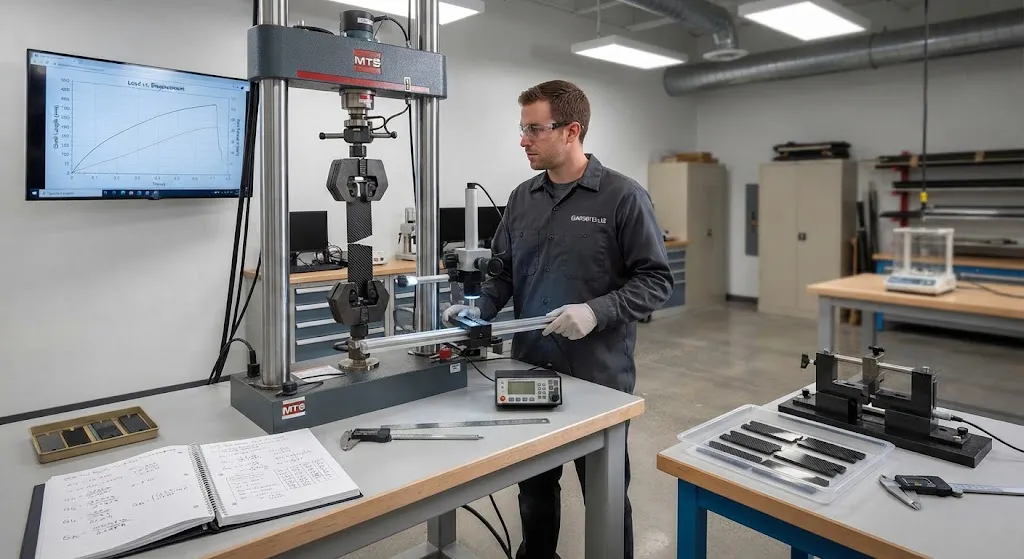
The double cantilever beam (DCB) test is the reference method for G1c. A unidirectional specimen with an embedded non-adhesive insert at the mid-plane is loaded in tension so the two beam halves peel apart, driving a crack along the interface. A traveling microscope or camera measures crack length while load and displacement are recorded, and the energy release rate at each point is computed from the compliance of the specimen. The critical value at initiation, and often the propagation value, defines G1c. The accepted procedure is ASTM D5528, with ISO 15024 as the equivalent international standard.
A well-run DCB test reveals more than a single number. Many epoxy systems show an R-curve, where G1c rises as the crack grows because fibers bridge across the crack faces and add a progressive pull-out contribution. Initiation values around the insert are the conservative design input, while propagation values better represent steady-state toughness. Reporting both, with the specimen dimensions used, lets a design team compare data from different suppliers without ambiguity.
Standard Test Methods: ENF and MMB for Mode II
Mode II fracture toughness is most commonly measured with the end-notched flexure (ENF) test. The specimen is the same unidirectional laminate with an insert at the mid-plane, but it is loaded in three-point bending so the crack faces slide in shear rather than peel apart. Compliance-based data reduction yields G2c at crack growth onset. The ENF geometry has a limitation — crack growth tends to be unstable beyond initiation — so propagation values are often captured with the four-point ENF variant or with the mixed-mode bending (MMB) apparatus defined by ASTM D6671, which applies a controlled ratio of mode I and mode II loading to a single specimen geometry.
Because real delaminations almost never grow in pure mode I or pure mode II, the failure envelope between the two is the practically useful result. MMB tests at several mode ratios, plotted as G1c versus mode mixity, show that toughness typically rises sharply as the mode II component increases. Design tools that model delamination growth, such as cohesive-zone finite element analyses, take this mixed-mode envelope as their input and use it to predict when an impact delamination will arrest or propagate under load.
How Resin Toughness Is Built In
Matrix chemistry is the primary lever on G1c and G2c, and the toughening strategies used commercially fall into a few families:
- Rubber toughening: Dissolved reactive liquid rubber precipitates as nano-scale particles during cure, cavitating ahead of the crack tip and dissipating energy. A cost-effective route that lifts G1c roughly two- to three-fold over the untoughened base resin.
- Thermoplastic toughening: A thermoplastic phase, such as polysulfone or polyetherimide, forms a semi-interpenetrating network that increases matrix ductility without the modulus penalty of rubber.
- Interleaf and particle interlayers: Toughening particles or thin thermoplastic films placed on the ply surface create a resin-rich interlaminar zone that absorbs crack energy locally, improving G1c and G2c with minimal effect on in-plane stiffness.
- Thermoplastic matrices: PEEK, PEKK, and polyetherimide systems have inherently high fracture toughness because the matrix deforms plastically over a large volume before failure, giving G1c values several times those of the toughest epoxies.
The trade-off is real: every toughening mechanism that raises G1c also raises viscosity, complicates out-of-autoclave processing, or adds cost. Toughened prepregs flow differently, particle interlayers change tack and drape, and thermoplastic systems require elevated-temperature consolidation. Selecting a system means balancing the measured fracture toughness against the process window the factory can actually hold.
Using Fracture Toughness Data in Design
Fracture toughness values enter engineering in three distinct places. First, material specification: minimum G1c and G2c values are written into resin and prepreg specifications so incoming lots are qualified on the property that governs damage tolerance, not just on stiffness and strength. Second, impact damage assessment: coupon-level tests relating impact energy to delamination area correlate strongly with G1c, so a tougher resin shrinks the expected damage size at a given impact energy, which in turn relaxes inspection and repair thresholds. Third, cohesive-zone modeling: delamination growth under complex loads is simulated with cohesive elements whose traction-separation behavior is calibrated from DCB and ENF data, allowing the certification test matrix to be supplemented with analysis rather than replaced by it.
For processors, the practical reading is simpler. If parts are seeing impact damage, tool drops, machining delamination, or edge cracking in trim operations, the first lever is resin toughness. A move from a standard epoxy to a toughened counterpart can multiply interlaminar fracture toughness by two to four times at a modest premium per kilogram, frequently eliminating the need for design changes or added ply counts.
Frequently Asked Questions
What are typical G1c and G2c values for carbon fiber epoxy laminates?
For a standard aerospace epoxy system, G1c typically falls between 150 and 300 J/m2 and G2c between 400 and 900 J/m2. Toughened epoxies reach 350-900 J/m2 in mode I and 900-2200 J/m2 in mode II, while thermoplastic matrices such as PEEK can exceed 900-1500 J/m2 in mode I. Exact numbers depend on the fiber-matrix interface, fiber volume fraction, and test method, so compare values only when they come from the same standard (ASTM D5528, ISO 15024, or ASTM D6671).
Why is G2c higher than G1c for the same material?
In mode I, the crack-tip region experiences high triaxial tension, which limits plastic deformation and lets the crack advance through a small, highly stressed zone. In mode II, shear loading blunts the crack tip and engages a larger volume of matrix and fiber in energy absorption, so more energy is required per unit area of crack growth. The ratio is typically two to three for carbon fiber composites, and it is normal for G2c to exceed G1c by a wide margin.
How can I increase the interlaminar fracture toughness of my part?
The highest-leverage options are switching to a rubber- or thermoplastic-toughened resin, adding an interleaf or particle interlayer to the layup, or moving to a thermoplastic matrix. Processing adjustments — such as avoiding excessive cure temperatures that degrade the toughening phase, and keeping fiber volume fraction consistent — help preserve the toughness the resin was designed to deliver. Where G1c data is missing, run DCB tests to the applicable standard before committing to a new material for a damage-tolerant application.
Conclusion
G1c and G2c fracture toughness translate resin chemistry into a measurable resistance to the delamination failures that dominate composite part life. DCB and ENF tests provide the data, and the mode I / mode II envelope feeds material specifications, impact damage assessments, and cohesive-zone analyses. For most applications, moving up one tier of resin toughness is the most direct route to better damage tolerance without adding plies or weight.
When selecting a resin or prepreg for an impact-tolerant application, ask your supplier for G1c and G2c data measured to a named standard. Browse our carbon fiber materials and prepreg range, or contact our engineering team to discuss fracture toughness requirements for your program.
Related Articles
- How Are Carbon Fiber Parts Made: Complete Guide
- Filament Wound Tube: Complete Guide
- Filament Wound FRP Pipe: Complete Guide
- Filament Wound Epoxy Tubes: Complete Guide
- Pultruded Carbon Fibre Rods: Cross-Sectional Properties and Standard Sizes
- Carbon Fiber Tube Fittings and Connectors: Joining Solutions for Structural Assemblies
Interested in Custom Carbon Fiber Products?
Contact our team for competitive pricing and technical specifications.
Get a QuoteRelated Products

Carbon Fiber Fishing Rod Blank
High-quality carbon fiber fishing rod blank manufactured from multiple grades of Toray carbon fiber cloth. Available in a wide range of lengths, powers, and actions for freshwater and saltwater applications. Suitable for OEM rod building.

Custom Carbon Fiber Medical Device Components
Medical-grade carbon fiber components manufactured for imaging equipment, surgical instruments, and patient support systems. Carbon fiber's radiolucency (X-ray transparency) and high strength-to-weight ratio make it ideal for CT scanner beds, wheelchair frames, surgical robot arms, and MRI-compatible accessories. Biocompatible resin systems available.
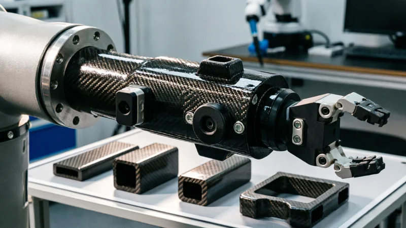
Carbon Fiber Robot End Effector Link — Custom Shape & Sensor Integration
Custom-shaped carbon fiber end effector links for robotic arms. Designed for automation integrators and research labs requiring lightweight, rigid connections between the robot wrist and gripper/tool. Can incorporate sensor mounting bosses, cable routing channels, and quick-change interfaces.

Custom Carbon Fiber Musical Instrument Parts
Carbon fiber components for musical instrument manufacturing offering superior dimensional stability, low weight, and consistent acoustic properties. We produce carbon fiber bows, guitar necks, violin chin rests, drum shells, and wind instrument bodies. Carbon fiber instruments are immune to humidity changes and temperature fluctuations that affect wooden instruments.
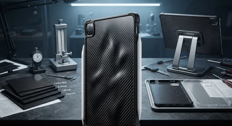
Carbon Fiber Tablet Case — Ultra-Light Protective Shell
Lightweight carbon fiber protective case for tablets and iPads. Molded from T700 3K prepreg with reinforced corner protection. Adds minimal weight while providing superior rigidity and drop protection compared to polycarbonate or silicone cases. Ideal for field workers, enterprise deployments, and professionals requiring durable tablet protection.