
When a composite part comes out of the mold, it is rarely the exact shape of the tool. Corners open up, flat panels bow, and flanges rotate away from the designed angle — a family of dimensional changes known collectively as warpage and spring-in. These distortions are not accidents. Th
Introduction
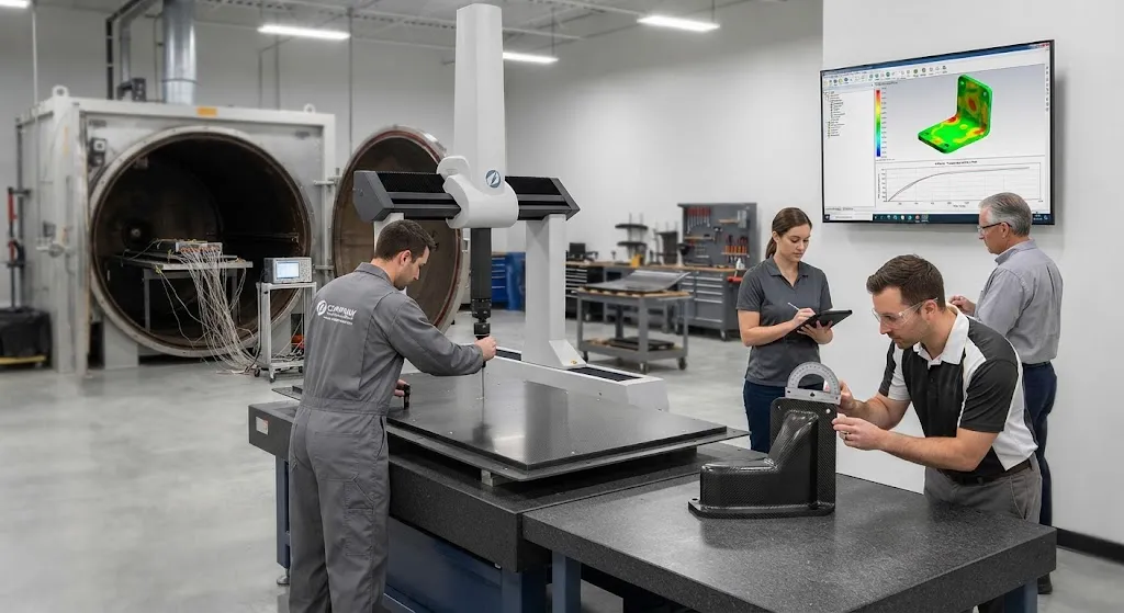
When a composite part comes out of the mold, it is rarely the exact shape of the tool. Corners open up, flat panels bow, and flanges rotate away from the designed angle — a family of dimensional changes known collectively as warpage and spring-in. These distortions are not accidents. They are the visible result of residual stress locked into the laminate during cure, caused by two mechanisms that every thermoset system shares: chemical shrinkage of the resin as it crosslinks, and thermal contraction as the part cools from the elevated cure temperature to room temperature.
For a part with tight tolerances, warpage determines whether the part fits its assembly jig, whether machining compensates or wastes material, and whether the design freeze survives first articles. This article explains the physics of cure shrinkage and residual stress, how they appear in measurements and simulation, and the practical process levers that move the final shape toward the drawing.
Where Shrinkage Comes From
Two physical mechanisms dominate residual stress development. Chemical shrinkage is the volumetric contraction of the resin during polymerization: epoxy and other thermosets shrink roughly 2-5 percent by volume as monomers crosslink into a network, though the stress-relevant part of that shrinkage happens after gelation, once the resin is solid enough to hold load. Thermal contraction is the second mechanism: the full part contracts as it cools from the cure temperature to room temperature over a range of typically 120-180 degrees Celsius for aerospace epoxies.
The stress arises from a mismatch. The carbon fibers are nearly rigid along their axis, with a coefficient of thermal expansion close to zero and no chemical shrinkage of their own. The resin, by contrast, shrinks chemically, contracts thermally at a coefficient 10-50 times that of the fibers, and is constrained by the fibers everywhere it is not free to move. Because the fibers and resin are locked together at the ply level, the resin contraction is resisted by the fibers, which places the matrix under residual tension and the laminate under a pattern of internal stresses that differs from ply to ply.
The table below summarizes the order-of-magnitude inputs that drive residual stress in a typical aerospace-grade composite:
| Source | Typical Magnitude | When It Acts |
|---|---|---|
| Resin volumetric cure shrinkage | 2-5% (epoxy) | Gelation to end of cure |
| Resin coefficient of thermal expansion | 45-65 x 10^-6 per C | Throughout cool-down |
| Fiber axial coefficient of thermal expansion | Near zero (slightly negative) | Throughout cool-down |
| Cure temperature to room temperature delta | 120-180 C | Cool-down phase |
The magnitudes explain why cure temperature matters so much: a part cured at 180 C carries substantially more thermal residual stress than the same part cured at 120 C, all else equal.
How Warpage and Spring-in Appear
The internal stress pattern converts into geometry changes at two characteristic scales. At the part level, asymmetric laminates bow and twist: a laminate with ply groups arranged asymmetrically through the thickness develops curvature because the shrinkage and thermal layers produce a net bending moment. Symmetric laminates avoid bending but still develop edge and corner effects. At the feature level, corner radii and flanges show spring-in — a tendency for the included angle to close — driven by the through-thickness stress gradient at an angled geometry, which makes a 90-degree corner come out closer to 88-89 degrees.
Measurement practice in production follows the same two scales. Flat panels are checked for bow and twist against a surface plate with feeler gauges or a coordinate measuring machine, and angle features are checked with digital protractors or shadow profiles. The repeatable part of the distortion, corrected for tooling variation, becomes the compensation input: tool angles are opened by the measured spring-in, and flat patterns are adjusted for curvature. What cannot be compensated by tooling alone must be reduced at the source, which is where process control enters.
Predicting Distortion with Process Simulation
Modern programs do not wait for first articles to discover warpage. Process simulation couples a thermochemical cure model with a structural analysis: the degree of cure and temperature field are computed through the cure cycle, the resulting cure shrinkage and thermal strain are mapped into the material model, and the residual stress state plus final deformed shape is solved. Commercial packages built on this approach predict spring-in and warpage within a practical tolerance band when the material model is calibrated with good shrinkage and modulus-vs-cure data.
The quality of the prediction depends on three inputs. First, the resin shrinkage-vs-degree-of-cure curve, measured by dilatometry or rheology-coupled methods, which captures how much shrinkage is released before in both liquid and gel states. Second, the development of modulus and glass transition temperature during cure, which determines when the laminate can hold stress. Third, the exact cure cycle and tooling constraints, because dwell times and cooling rates change the stress history. Programs that validate these inputs against a few instrumented parts achieve predictions reliable enough to design compensation into the tool before steel is cut.
Mitigation Levers: What Actually Moves the Part
Several process levers reduce residual stress and warpage, and they operate at different points in the process. The choices below are ordered from highest practical impact to nicest-to-have:
- Optimize the cool-down: Slower, staged cooling lets the laminate stress relax more as it passes through the glass transition region, reducing locked-in thermal stress. A controlled 1-3 C per minute cool-down through the transition is a standard production lever.
- Match tooling coefficient of thermal expansion: Invar and low-CTE tools minimize the tooling-induced component of distortion, particularly for flat panels and tool-side-critical features; the higher tool cost pays off when tolerances are tight.
- Select a lower-shrinkage resin: Resin formulations with reduced cure shrinkage, including some toughened and low-profile systems, release less chemical stress; the trade-off is usually mechanical performance or processing latitude.
- Adjust the cure cycle: Lower cure temperature and a longer dwell reduce the thermal delta and change the shrinkage release timing; the cost is longer cycle time in the autoclave or oven.
- Compensate the tool geometry: Open tool angles by the measured or predicted spring-in and modify flat patterns for predicted curvature; this converts predictable distortion into a correct final shape without changing the process.
In practice, compensation and cool-down control do most of the work, and resin selection and tooling CTE handle the residual. Programs that combine all four report dimensional yield improvements that routinely make the difference between a first-article pass and a rework loop.
Frequently Asked Questions
How much does a composite part typically warp or spring in?
Spring-in for a 90-degree corner in a carbon fiber epoxy laminate commonly measures 1-3 degrees, depending on the corner radius, laminate thickness, and cure temperature. Flat panels of modest size typically bow by fractions of a millimeter per meter, but large thin panels in asymmetric layups can twist and bow several millimeters. The exact numbers depend strongly on the material system and cure cycle, which is why programs measure the distortion on representative parts and feed the results back into tool compensation.
Can cure shrinkage be eliminated entirely?
No. Every crosslinking thermoset shrinks chemically, and every part contracts thermally on cool-down — the two mechanisms are inherent to thermoset processing. What can be reduced is the stress locked in: slower cool-down through the glass transition region, lower cure temperature, low-CTE tooling, and resin systems with reduced shrinkage all lower the final residual stress. The residual that remains is then handled by tool compensation, which adjusts for the predictable distortion instead of fighting it.
Is simulation accurate enough to design compensation before building tools?
Yes, when the material model is calibrated. With good resin shrinkage-versus-cure data, modulus development, and the actual cure cycle, commercial process simulation predicts spring-in and warpage within a practical tolerance band — commonly within a degree for angle features and within a fraction of a millimeter for panel deflection on well-characterized systems. The caveat is that the accuracy depends on input quality: uncalibrated or generic material data can mislead, so programs validate the model against instrumented panels before trusting it for tool design.
Conclusion
Cure shrinkage and thermal contraction are not defects to be eliminated — they are inherent physics of thermoset composites that must be understood, predicted, and managed. The practical toolkit is well established: characterize the resin's shrinkage and modulus development, simulate the process to predict distortion, control cool-down and cure temperature to reduce locked-in stress, and compensate the tool for the predictable remainder. Programs that apply all four consistently turn first-article surprises into routine dimensional compliance.
When warpage is putting your first articles at risk, data beats guesswork. Review our carbon fiber materials and process support, or contact our engineering team to discuss material data resources and distortion control for your program.
Related Articles
- Filament Wound FRP Pipe: Complete Guide
- Filament Wound Epoxy Tubes: Complete Guide
- Pultruded Carbon Fibre Rods: Cross-Sectional Properties and Standard Sizes
- Carbon Fiber Tube Fittings and Connectors: Joining Solutions for Structural Assemblies
- Carbon Fiber Plate Insert: Threaded Insert Design for Composite Structures
- Filament Wound Epoxy Tubing: Selection Guide for Industrial and Aerospace Applications
Interested in Custom Carbon Fiber Products?
Contact our team for competitive pricing and technical specifications.
Get a QuoteRelated Products

Carbon Fiber Fishing Rod Blank
High-quality carbon fiber fishing rod blank manufactured from multiple grades of Toray carbon fiber cloth. Available in a wide range of lengths, powers, and actions for freshwater and saltwater applications. Suitable for OEM rod building.

Custom Carbon Fiber Medical Device Components
Medical-grade carbon fiber components manufactured for imaging equipment, surgical instruments, and patient support systems. Carbon fiber's radiolucency (X-ray transparency) and high strength-to-weight ratio make it ideal for CT scanner beds, wheelchair frames, surgical robot arms, and MRI-compatible accessories. Biocompatible resin systems available.
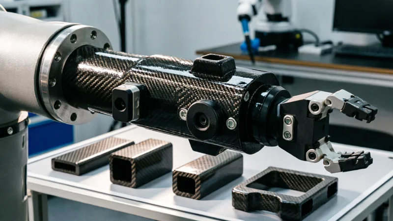
Carbon Fiber Robot End Effector Link — Custom Shape & Sensor Integration
Custom-shaped carbon fiber end effector links for robotic arms. Designed for automation integrators and research labs requiring lightweight, rigid connections between the robot wrist and gripper/tool. Can incorporate sensor mounting bosses, cable routing channels, and quick-change interfaces.

Custom Carbon Fiber Musical Instrument Parts
Carbon fiber components for musical instrument manufacturing offering superior dimensional stability, low weight, and consistent acoustic properties. We produce carbon fiber bows, guitar necks, violin chin rests, drum shells, and wind instrument bodies. Carbon fiber instruments are immune to humidity changes and temperature fluctuations that affect wooden instruments.
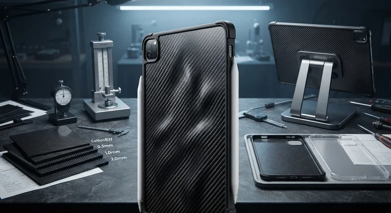
Carbon Fiber Tablet Case — Ultra-Light Protective Shell
Lightweight carbon fiber protective case for tablets and iPads. Molded from T700 3K prepreg with reinforced corner protection. Adds minimal weight while providing superior rigidity and drop protection compared to polycarbonate or silicone cases. Ideal for field workers, enterprise deployments, and professionals requiring durable tablet protection.