
Conventional composite laminates are built from straight unidirectional plies at fixed angles — 0, 45, 90 and their negatives — and this fixed-angle architecture limits what a laminate can do. Loads arriving between the fiber directions are carried partly by the resin matrix, and geomet
Introduction
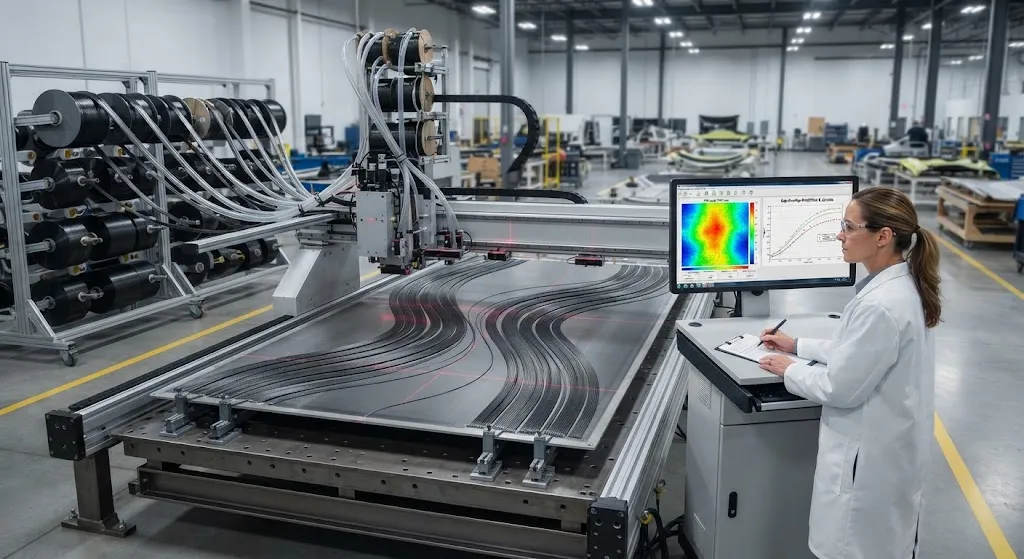
Conventional composite laminates are built from straight unidirectional plies at fixed angles — 0, 45, 90 and their negatives — and this fixed-angle architecture limits what a laminate can do. Loads arriving between the fiber directions are carried partly by the resin matrix, and geometric instabilities such as buckling are resisted only by the laminate stiffness distribution that the discrete angle choices create. An automated fiber placement (AFP) machine, however, does not have to lay straight tows. By steering each tow along a curved path within the ply plane, it produces variable-stiffness laminates whose elastic properties change continuously across the panel, opening a design freedom that fixed-angle laminates cannot reach.
The payoff is documented across university and industry programs: variable-stiffness panels reported buckling loads 20-40 percent higher than equivalent straight-fiber panels at the same mass, together with measurable gains in damage tolerance because steered crack paths deflect around fiber curvature. This article explains where the gains come from structurally, what the manufacturing limits are, and how a design team decides whether fiber steering earns its place in a production program.
How Fiber Steering Creates Variable Stiffness
In a steered ply, the fiber angle varies continuously with position. A linear steering path is described by describing the fiber angle as a function of position: for a panel spanning the x-direction, the angle theta typically varies linearly from an off-axis value at one end to another at the other end. The result is a laminate where the stiffness matrix changes point to point, so the load path can be shaped rather than accepted. AFP machines steer tows by controlling the steering radius of the tow course; the physical limit is the minimum turning radius below which the inner edge of the tow becomes overloaded, buckles, or gaps open between adjacent courses.
Two manufacturing realities shape what designers can specify. First, the minimum steering radius is typically 300-800 millimeters for a 6.35-millimeter tow, tighter for thinner tows and looser for wider ones. Second, curved courses create gaps and overlaps where adjacent tows diverge and converge; gaps must be filled to avoid resin-rich zones, and overlaps must be managed because they add local thickness. Design tools now predict gap-overlap maps during the definition phase, so the stiffness distribution is designed together with the geometry that the machine can actually lay.
Buckling Load Improvements
The buckling benefit is the most consistently reported advantage of variable-stiffness laminates. A plate under compressive or shear loading buckles when its load exceeds a critical level set by its stiffness distribution; because steering moves stiffness to where the buckling mode shape needs it, the critical load rises for the same mass of material. The table below compares published results from a representative set of steered and straight-fiber panels:
| Panel Configuration | Buckling Load (Relative) | Improvement Over Straight-Fiber | Loading |
|---|---|---|---|
| Straight-fiber quasi-isotropic, baseline | 100 | — | Compression |
| Linearly steered 0 to 45 degrees | 120-140 | 20-40% | Compression |
| Steered with constant-curvature path | 112-125 | 12-25% | Compression |
| Steered panel under pure shear | 110-130 | 10-30% | Shear |
The magnitude of the gain depends on the loading case, the panel aspect ratio, and the steering amplitude. Gains cluster in the 20-40 percent range for compression-dominated panels and are smaller but still positive under shear. Because buckling is a stiffness-driven instability rather than a strength failure, the improvement is achieved without adding mass — the same panel weight buys a higher load-carrying capability, which is why skin-stringer panels for aircraft wing and fuselage skins are the leading application candidate.
Damage Tolerance Gains
Damage tolerance improves for a different reason: crack path control. In a straight-fiber laminate, an impact-induced delamination or a matrix crack grows along the fiber direction of the ply it is in, following the straight continuous path of least resistance. In a steered laminate, the fibers curve, so a crack propagating along the local fiber direction continuously changes trajectory. Published studies report that steered laminates arrest or deflect delamination at steering boundaries, reduce the size of impact damage areas, and shift the onset of visible damage to higher loads.
- Delamination deflection: The changing fiber angle makes the driving force at a crack tip vary along its length, so delamination fronts curve and slow, increasing the energy required for growth.
- Reduced impact damage area: Steered panels in tests show impact damage areas 15-30 percent smaller than straight-fiber equivalents at the same impact energy, because the curved stiffness distribution spreads impact energy through a larger volume.
- Better compression-after-impact (CAI) retention: With smaller damage area and deflected delaminations, CAI strength retention is typically 5-15 percent higher — the property that governs inspection thresholds and repair decisions in service.
These gains are real but sensitive to layup details, so damage tolerance improvements are validated coupon-by-coupon rather than assumed from the buckling data.
Manufacturing Constraints and Defects
Fiber steering imposes costs that a production program must price in. The minimum radius constraint limits how aggressive a stiffness distribution can be; tighter radii would require narrower tows, which place slower and multiply course count. Gap-overlap management adds process planning work and can create thickness variation that complicates assembly tolerance. In-situ inspection — laser line scanners and thermal imaging on AFP heads — is becoming standard to catch tow buckling and gaps before they are buried in the laminate.
Defect sensitivity is the opposing consideration. Steered tows are more likely to show wrinkle and local buckling defects than straight courses, and out-of-plane waviness is the defect type that most degrades compression strength. Programs therefore pair steering with automated defect detection and set acceptance criteria derived from strength knock-down testing, the same way straight-fiber wrinkles are handled today.
Design and Qualification Workflow
- Define the stiffness distribution: Finite-element optimization tools parameterize the fiber angle field and solve for the distribution that maximizes the target response — buckling load, CAI, or a weighted combination — under the steering radius constraint.
- Generate the machine path: The steering plan is translated into tow courses, gap-overlap maps are computed, and the layup sequence is fixed with the process team.
- Build and test coupons: Steered panels are tested in compression, shear, and CAI against the straight-fiber baseline; the knock-down factors and improvement margins from these tests become the design allowables.
- Demonstrate traceability: Each panel's steering program, gap map, and inspection record are archived, matching the qualification evidence standard for the application — structural, space, or automotive.
This workflow fits inside an existing AFP qualification program. The incremental cost is the optimization and path-definition work plus defect inspection; the payoff is the 20-40 percent buckling improvement or an equivalent mass reduction that no fixed-angle laminate can reach.
Frequently Asked Questions
How much buckling load improvement can fiber steering realistically deliver?
Published data consistently show 20-40 percent buckling load improvements for steered panels compared with straight-fiber panels of the same mass, with the larger gains in compression-dominated panels. The improvement depends on the steering amplitude, panel aspect ratio, and loading case; panels under pure shear see 10-30 percent, and panels with modest steering angles fall at the bottom of the range. Because buckling is stiffness-driven, the gain is achieved without mass addition — the design intent is usually a mass reduction at constant load capability.
What limits how sharply fiber tows can be steered?
The physical limit is the minimum steering radius, below which the tow's inner edge buckles or gaps open between courses. For a standard 6.35-millimeter AFP tow the practical minimum radius is roughly 300-800 millimeters; narrower tows steer tighter, wider tows require larger radii. Aggressive stiffness distributions also generate gap-overlap patterns that must be filled or managed, and these process constraints are folded into the optimization so the designed stiffness field is actually layable.
Do steered laminates hold up under impact better than straight-fiber laminates?
Generally yes. Because the stiffness field curves, impact energy spreads through a larger volume and delamination fronts deflect and slow at steering boundaries. Coupon tests typically show 15-30 percent smaller impact damage areas and 5-15 percent higher compression-after-impact strength retention than straight-fiber counterparts at the same impact energy. The improvements are consistent but layup-sensitive, so they are validated by testing rather than assumed.
Conclusion
Variable-stiffness laminates made by AFP fiber steering convert the stiffness distribution of a composite panel from a fixed grid into a design variable, with measured consequences: 20-40 percent higher buckling loads, 15-30 percent smaller impact damage areas, and improved compression-after-impact retention at the same mass. The manufacturing constraints — minimum steering radius, gap-overlap management, and defect sensitivity — are now well enough understood that the technology has moved from research into production evaluation for aircraft skin panels and damage-tolerant structures.
For structural engineers assessing fiber steering, the decision framework is straightforward: compare the steering benefit against the qualification cost of steered coupons and process inspection. Explore our carbon fiber tow and automated layup material range, or contact our engineering team to discuss material formats and test data for your variable-stiffness program.
Part of topic
Related Articles
- Filament Wound FRP Pipe: Complete Guide
- Filament Wound Epoxy Tubes: Complete Guide
- Pultruded Carbon Fibre Rods: Cross-Sectional Properties and Standard Sizes
- Carbon Fiber Tube Fittings and Connectors: Joining Solutions for Structural Assemblies
- Carbon Fiber Plate Insert: Threaded Insert Design for Composite Structures
- Filament Wound Epoxy Tubing: Selection Guide for Industrial and Aerospace Applications
Interested in Our Products?
Contact our team for competitive pricing and technical specifications.
Get a QuoteRelated Products

Carbon Fiber Fishing Rod Blank
High-quality carbon fiber fishing rod blank manufactured from multiple grades of Toray carbon fiber cloth. Available in a wide range of lengths, powers, and actions for freshwater and saltwater applications. Suitable for OEM rod building.

Carbon Fiber Plate — 3K Twill T700 3.0mm
Medium-thickness 3.0mm carbon fiber plate offering significantly higher load capacity while maintaining attractive 3K twill finish. Suitable for structural brackets, reinforcement plates, and load-bearing panels.

Custom Carbon Fiber Medical Device Components
Medical-grade carbon fiber components manufactured for imaging equipment, surgical instruments, and patient support systems. Carbon fiber's radiolucency (X-ray transparency) and high strength-to-weight ratio make it ideal for CT scanner beds, wheelchair frames, surgical robot arms, and MRI-compatible accessories. Biocompatible resin systems available.

Carbon Fiber Plate — 3K Twill T700 1.5mm
Thin 1.5mm carbon fiber plate with 3K twill weave surface. Lightweight and stiff, commonly used for covers, panels, drone bodies, and applications requiring a premium aesthetic appearance.

Square Carbon Fiber Tube — 3K Twill T700
Square cross-section carbon fiber tube manufactured with 3K twill weave for torsional strength. Preferred for structural frames, trusses, and support columns where rectangular geometry offers design flexibility.