
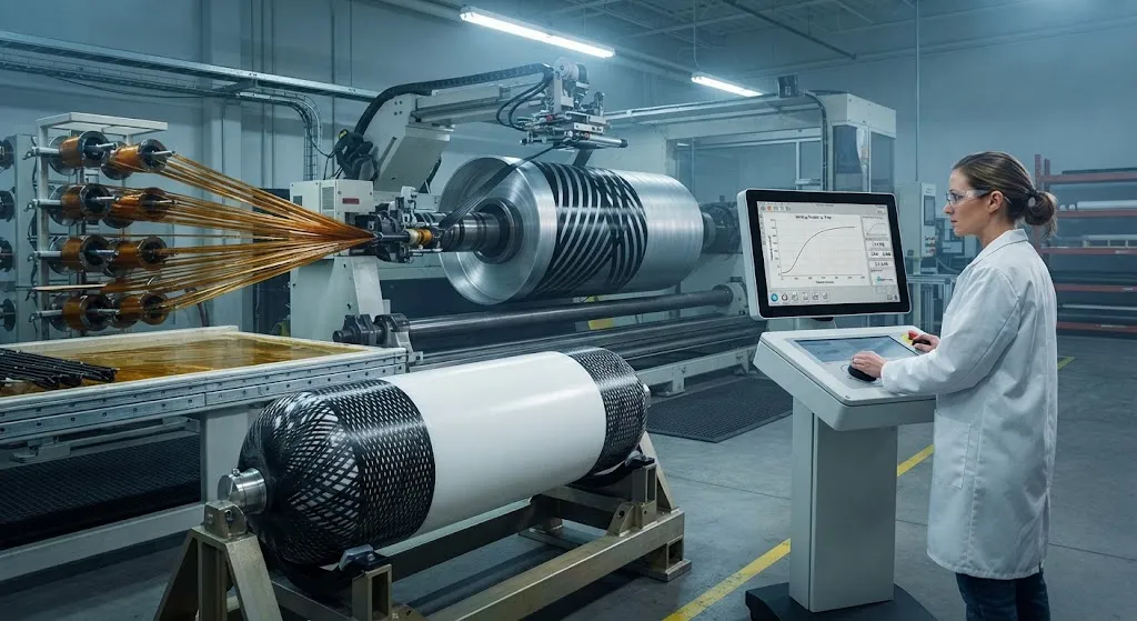
Filament winding is the dominant manufacturing process for Type IV hydrogen pressure vessels, the composite overwrapped tanks used in fuel cell vehicles, hydrogen refueling stations and transport trailers. Demand is expanding rapidly: the global Type IV hydrogen vessel market was valued
Introduction
Filament winding is the dominant manufacturing process for Type IV hydrogen pressure vessels, the composite overwrapped tanks used in fuel cell vehicles, hydrogen refueling stations and transport trailers. Demand is expanding rapidly: the global Type IV hydrogen vessel market was valued at approximately 1.28 billion US dollars in 2026 and is forecast to grow at a compound annual rate of 24.6 percent through the early 2030s. Yet the process parameter that most directly controls structural performance — carbon fiber tension during winding — receives far less attention in engineering handbooks than fiber selection or laminate design.
Tension determines how tightly each carbon tow is packed against the layer below it, which in turn sets fiber volume fraction, void content, fiber straightness and the load path through the laminate. The consequences are highly measurable: tank manufacturers report burst pressure differences of 8-15 percent between laminates wound at low tension and those wound inside the optimal tension window, at identical fiber weight. This article explains the mechanics of tension control, the interaction of tension with geodesic and non-geodesic winding paths, and the practical implications for Type IV vessel burst performance.
Why Fiber Tension Is the Governing Process Parameter
In wet winding, carbon fiber tows pass through a resin bath and then travel under tension to a rotating mandrel. The tension applied at the payout eye serves three structural functions:
- Packing density: Tension compresses the freshly applied ply against the previous ones, squeezing excess resin toward the surface and increasing fiber volume fraction toward the 60-65 percent range typical of high-performance pressure vessels.
- Fiber straightness: Uniform tension keeps each filament straight and aligned with the intended winding angle, preserving the full tensile modulus of the fiber under load.
- Interlayer compaction: Tension force normal to the surface improves interlayer contact during cure, reducing the resin-rich interlayer zones where delamination initiates.
Each of these functions is sensitive to tension in a different way, which is why a single optimal tension value is rarely correct — the right setpoint depends on tow count, resin viscosity, mandrel geometry and winding speed.
How Tension Drives Laminate Quality and Fiber Volume Fraction
The relationship between tension and laminate quality is well documented in winding research and production data. The table below summarizes typical effects observed with 12K carbon tow in wet winding of cylindrical vessel sections:
| Tension Level | Fiber Volume Fraction | Void Content | Fiber Waviness | Relative Burst Pressure |
|---|---|---|---|---|
| Low (below 5 N per 12K tow) | 52-56% | 1.5-3.0% | Low | Baseline -10 to -15% |
| Optimal (8-14 N per 12K tow) | 60-65% | Below 1.0% | Minimal | Baseline (100%) |
| High (above 18 N per 12K tow) | 64-67% | 0.3-0.8% | Significant misalignment | Baseline -5 to -10% |
Low tension leaves voids and a low fiber volume fraction, so the laminate carries load partly through resin. High tension can be equally damaging: excessive tension stretches and misaligns filaments during crossing, creating fiber waviness and broken tows at the dome turnaround regions. The optimal window keeps fiber volume fraction near 62-65 percent without inducing waviness, which is why modern winding machines control tension dynamically rather than holding a single static setpoint.
Tension Control Hardware: From Creel to Payout
Controlling tension in practice requires attention at every station along the fiber path:
- Creel tensioners: Each bobbin runs through a dancer-arm or magnetic particle brake tensioner that establishes baseline tension before the band enters the resin bath.
- Resin bath drag: Viscosity and bath depth add uncontrolled drag, so tension is re-measured after the bath with a load cell roller before deposition.
- Closed-loop payout control: Servo-driven payout eyes adjust speed to maintain constant tension as the winding angle changes between hoop and helical passes, compensating for the changing effective fiber speed.
- Lubrication and guide wear: Worn ceramic guides and non-uniform resin pick-up create tension transients that show up later as local voids and porosity bands.
Modern control systems sample tension at 100-1000 Hz and correct within tens of milliseconds, holding variation within 1-2 N of setpoint even at winding speeds above 60 meters per minute.
Geodesic and Non-Geodesic Path Design
Tension control cannot be optimized in isolation from path design. A geodesic path is the shortest, friction-free route over a curved surface; when a tow follows a geodesic, fiber tension contributes no lateral force and the tow is inherently stable. Most cylindrical vessel bodies are wound with near-geodesic helical paths, where the tension simply keeps the tow taut on the surface.
Non-geodesic paths deliberately deviate from the geodesic, using friction between fibers to hold the tow in a position that a free pathway could not maintain. The governing equation relates the slip coefficient to the local change in winding angle: for carbon fiber on a resin-coated surface, effective friction coefficients typically range from 0.1 to 0.3. Non-geodesic winding is used to achieve variable-angle domes and to reduce turnaround band stacking at the boss region — but it demands stable, higher tow tension because lower tension reduces the normal force that generates the friction needed to prevent slippage. Designers therefore specify tension jointly with path geometry: an aggressive non-geodesic trajectory may require 20-30 percent higher tension than a near-geodesic trajectory, and the setpoint must be re-verified whenever the path program changes.
Measured Impact on Type IV Vessel Burst Performance
The structural consequences of tension control show up most clearly in burst testing. For a commercial Type IV tank with a 700-bar design pressure and a typical 2.25 safety factor, burst testing at 1575 bar is a pass-or-fail gate that directly reflects laminate quality. Production data and published studies converge on the following relationships:
- Moving from low tension (resin-rich laminates) to the optimal window recovers 10-15 percent of burst pressure at constant fiber mass — equivalent to the entire safety margin of some designs.
- Over-tensioned laminates show premature fiber breakage at dome turnarounds, reducing burst pressure 5-10 percent and shifting failure initiation from the expected helical band to the turnaround region.
- Tension variation exceeding 3 N across a single pressure layer correlates with localized void bands that become the crack-initiation sites in cyclic pressure testing, reducing fatigue life by a factor of two in accelerated hydrogen cycling tests.
Because burst pressure scales with fiber volume fraction and fiber efficiency, and both are governed by tension, tank programs conservatively rank tension control alongside fiber selection and resin system class as the three variables that must be locked before certification testing begins.
Process Monitoring and Quality Assurance
Production-quality tension control requires verification beyond the machine readout. Effective QA programs combine three layers of evidence:
- In-process records: Continuous tension logging per tow, band, and layer, retained alongside cure cycles for traceability on every vessel serial number.
- First-article laminate checks: Acid digestion to measure fiber volume fraction, micrograph sectioning for voids, and X-ray computed tomography on sample layers to confirm waviness and interlayer compaction.
- Correlation to burst data: Tracking burst test results against the logged tension history of production vessels, so the tension window is validated against actual structural outcomes rather than assumed from lab coupons.
For qualification programs, winding trials should map the full tension window — low, optimal and high — on instrumented test vessels before the production envelope is frozen, rather than trusting a single nominal setpoint.
Frequently Asked Questions
What is the typical winding tension for carbon fiber in a Type IV hydrogen vessel?
For a standard 12K carbon tow, typical wet-winding tension ranges from 8 to 14 N per tow. Larger 24K tows are wound at roughly 16-28 N, and heavy-tow 48K-60K products require proportionally higher tension. The correct value depends on resin viscosity, winding speed and mandrel curvature: the practical method is to run a tension sweep and measure fiber volume fraction and void content to find the plateau where both are optimal.
Why does excessive tension reduce burst pressure even though fiber volume fraction increases?
Beyond the optimal point, higher tension induces fiber misalignment and waviness as tows cross the dome regions and fiber tension redistributes locally. Wavy fibers cannot reach their full tensile modulus along the loading direction, and over-tensioned tows can fracture at the turnaround. The result is a laminate that is denser but structurally less efficient — measured burst pressure declines 5-10 percent despite a higher fiber volume fraction.
How is winding tension measured during production?
Production machines measure tension with load-cell rollers placed after the resin bath, sampling at 100-1000 Hz and feeding a closed loop that adjusts the servo-driven payout speed. Creel-side dancer arms set baseline tension before the resin bath, and modern systems log continuous per-tow tension records for each vessel. These records form part of the QA traceability package and are correlated with burst test results to validate the tension window.
Conclusion
Carbon fiber tension during filament winding is not a secondary detail — it is the variable that converts expensive aerospace-grade fiber into burst-capable vessel structure. Winding inside the optimal tension window recovers 10-15 percent of burst pressure versus resin-rich laminates, and tension discipline throughout creel, bath and payout determines fiber volume fraction, void content and fiber straightness in equal measure. For a market growing at nearly 25 percent annually, Type IV tank programs that lock tension control before certification testing gain predictable burst margins and longer fatigue life.
For vessel manufacturers evaluating material supply and process design, practical support begins with the carbon fiber itself. Explore our range of winding-grade carbon fiber tows, or contact our engineering team to discuss tension windows and qualification data for your Type IV program.
Part of topic
Related Articles
- Pultruded Carbon Fibre Rods: Cross-Sectional Properties and Standard Sizes
- Carbon Fiber Tube Fittings and Connectors: Joining Solutions for Structural Assemblies
- Carbon Fiber Plate Insert: Threaded Insert Design for Composite Structures
- Filament Wound Epoxy Tubing: Selection Guide for Industrial and Aerospace Applications
- Filament Wound Epoxy Tubes Advantages: Over Metal and Pultruded Alternatives
- Carbon Fiber Tube Strength: Analysis Methods and Design Allowables
Interested in Our Products?
Contact our team for competitive pricing and technical specifications.
Get a QuoteRelated Products

Carbon Fiber Fishing Rod Blank
High-quality carbon fiber fishing rod blank manufactured from multiple grades of Toray carbon fiber cloth. Available in a wide range of lengths, powers, and actions for freshwater and saltwater applications. Suitable for OEM rod building.

Carbon Fiber Plate — 3K Twill T700 1.5mm
Thin 1.5mm carbon fiber plate with 3K twill weave surface. Lightweight and stiff, commonly used for covers, panels, drone bodies, and applications requiring a premium aesthetic appearance.

Carbon Fiber Plate — 3K Twill T700 3.0mm
Medium-thickness 3.0mm carbon fiber plate offering significantly higher load capacity while maintaining attractive 3K twill finish. Suitable for structural brackets, reinforcement plates, and load-bearing panels.

Custom Carbon Fiber Medical Device Components
Medical-grade carbon fiber components manufactured for imaging equipment, surgical instruments, and patient support systems. Carbon fiber's radiolucency (X-ray transparency) and high strength-to-weight ratio make it ideal for CT scanner beds, wheelchair frames, surgical robot arms, and MRI-compatible accessories. Biocompatible resin systems available.

Square Carbon Fiber Tube — 3K Twill T700
Square cross-section carbon fiber tube manufactured with 3K twill weave for torsional strength. Preferred for structural frames, trusses, and support columns where rectangular geometry offers design flexibility.