
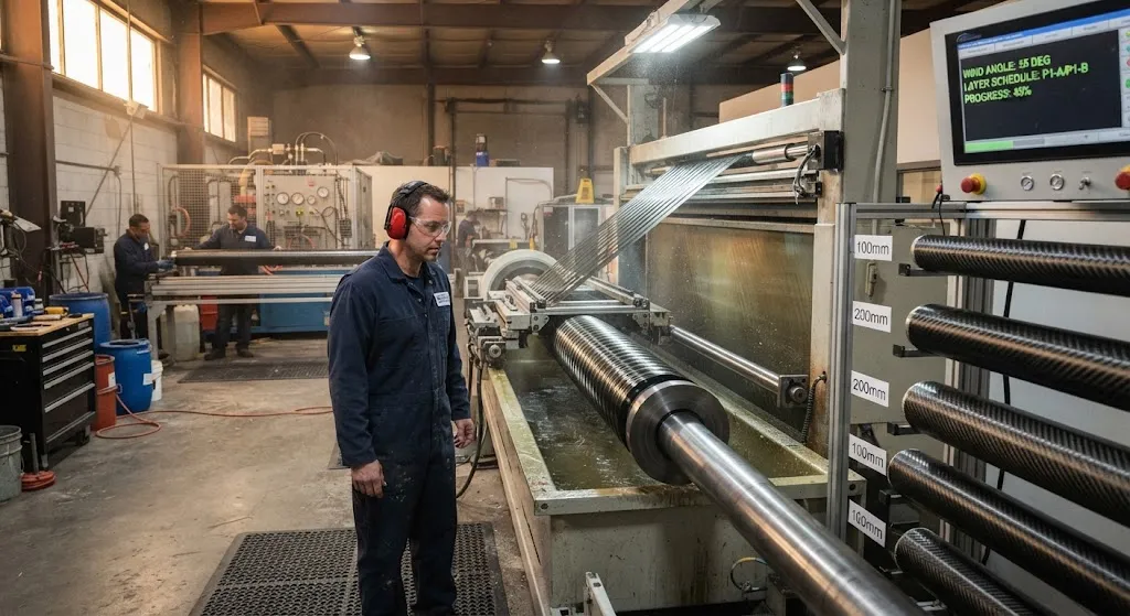
Filament wound tubes are composite tubes produced by winding continuous fibre rovings, wetted with resin, onto a rotating mandrel at a controlled angle until the required wall thickness is built up. Unlike pultrusion, which pulls straight fibres along a die, filament winding lays each band of fibre
Introduction
Filament wound tubes are composite tubes produced by winding continuous fibre rovings, wetted with resin, onto a rotating mandrel at a controlled angle until the required wall thickness is built up. Unlike pultrusion, which pulls straight fibres along a die, filament winding lays each band of fibre on a precise helical path, so the finished filament wound tubes can be tuned to carry hoop stress, axial load, or torsion simply by changing the winding angle. That design freedom is why pressure vessels, drive shafts, rocket motor cases, and chemical piping all rely on filament winding. A filament wound tube is a structural element built from the fibre up, and the winding pattern recorded in the machine programme is what decides its final performance.
This guide explains the winding process, how angle drives properties, the materials and resins involved, and the specifications buyers should define when sourcing filament wound tubes.
How Filament Wound Tubes Are Made
The process has four moving parts that must be controlled together:
- Mandrel: A steel or aluminium mandrel sets the internal diameter and surface finish. It may stay as a liner, or be extracted after cure for a hollow tube.
- Fibre delivery: Roving is pulled from creels, tensioned, and passed through a resin bath or a pre-impregnated tow before reaching the delivery eye.
- Winding machine: The mandrel rotates while the carriage carrying the delivery eye travels along its length, so the fibre is laid in a helix whose angle is set by the ratio of carriage speed to mandrel speed.
- Cure: Once the designed layers are complete, the part cures at room temperature or in an oven, after which the mandrel is removed and the ends are machined.
Because the fibre is laid continuously, there are no cut tow ends inside the wall and no splices, which gives filament winding one of the highest fibre volume fractions of any composite process, typically 60 to 70 percent by volume. That continuous path is also why filament wound tubes are stronger per unit weight than a hand-laid tube of the same fibre.
How Winding Angle Controls Filament Wound Tube Properties
The winding angle, measured from the mandrel axis, is the single most powerful design variable. Fibre carries load only along its length, so the angle decides which direction the tube resists:
| Winding Angle | Pattern Name | Strength Bias | Typical Application |
|---|---|---|---|
| 85-90 degrees | Hoop | Hoop stress dominant | Pressure vessels, pipes, tanks |
| 55-75 degrees | Helical | Balanced hoop and axial | General structural tubes |
| 30-54 degrees | Helical | Axial and torsion | Drive shafts, torsion tubes |
| 10-30 degrees | Low-angle helical | Axial dominant | Push rods, struts, boom tubes |
| Polar (90 at ends) | Dome closure | Closes vessel ends | Pressure vessel domes |
A pure hoop winding at 90 degrees gives maximum burst pressure but almost no axial strength, so a closed-end pressure vessel combines hoop layers for the cylindrical body with low-angle helical layers that carry the axial load and turn down into the domes. The classical netting analysis rule for a thin-walled pressure vessel is a 54.7 degree angle, the point where hoop and axial stress are carried equally by one fibre direction. Real designs go beyond the simple rule and use finite element analysis, but the 54.7 degree reference remains a useful starting point for a balanced tube under internal pressure.
Materials Used in Filament Wound Tubes
Fibre and resin selection sets the property ceiling, and the two are chosen together with the winding angle:
| Fibre | Tensile Strength | Tensile Modulus | Best Used For |
|---|---|---|---|
| E-glass | About 2400 MPa | About 73 GPa | Low-cost pipes, poles, tanks |
| T300 carbon | About 3530 MPa | About 230 GPa | General structural tubes |
| T700 carbon | About 4900 MPa | About 230 GPa | High-performance shafts and vessels |
| High-modulus carbon | About 3500 MPa | About 300 GPa and above | Stiffness-critical booms and spars |
| Aramid | About 3600 MPa | About 131 GPa | Impact, ballistic, and abrasion resistance |
The resin matrix holds the fibres and transfers load between them. Epoxy gives the best mechanical properties and low shrinkage, vinyl ester offers chemical resistance for pipes, and polyester is used for low-cost, large-diameter tubes where strength is secondary. A common choice for structural filament wound tubes is epoxy with T700 carbon at a helical angle, which balances strength and cost for shafts and struts.
Advantages and Limitations of Filament Wound Tubes
The process has real strengths, but its limits should be understood before designing around it:
- High fibre volume fraction: Continuous fibre winding reaches 60 to 70 percent fibre by volume, giving high strength and stiffness per unit weight.
- Tunable anisotropy: Winding angle lets one machine produce vessels, shafts, and struts by changing the programme.
- Continuous reinforcement: No cut ends or splices inside the wall means fewer weak points and better fatigue performance than hand lay-up.
- Not good for complex shapes: Filament winding suits surfaces of revolution such as cylinders and spheres. Flat panels and sharp corners go to other processes.
- Mandrel cost: A dedicated mandrel is needed for each diameter, which raises the effective cost for short production runs.
- Surface finish: The outer surface carries the helical fibre texture and usually needs sanding, painting, or a gel coat for appearance.
Sourcing Filament Wound Tubes
When buying filament wound tubes, define the following in writing so the supplier can programme the winding correctly:
| Specification Item | What to Define | Why It Matters |
|---|---|---|
| Inside diameter and wall thickness | Exact ID, OD, and tolerance | Sets fit with mating parts |
| Fibre and grade | E-glass, T300, T700, or high modulus | Determines strength and stiffness |
| Winding angle and layup | Angle sequence and layer count | Controls load direction and burst pressure |
| Resin system | Epoxy, vinyl ester, or polyester | Sets temperature and chemical resistance |
| Load case | Hoop, axial, torsion, or bending | Guides angle selection |
| Validation data | Burst, tensile, or stiffness test report | Confirms the tube meets the design load |
Most buyers begin with a search for filament wound tubes near me or for filament wound tubes suppliers, and many then compare a regional winder with a filament wound tubes USA supplier on lead time and validation support. Whichever route you take, ask for a burst or tensile test report on a production-representative sample before committing to volume, and confirm the winding angle schedule is recorded in the drawing, because a tube made to a different angle can look identical while carrying load in the wrong direction. For pressure service, ask specifically whether the domes are wound integrally or bonded on, since that detail drives burst performance far more than the cylinder wall thickness.
Frequently Asked Questions
What is the best winding angle for a filament wound tube?
There is no single best angle; it depends on the load. For internal pressure, hoop layers near 90 degrees carry the hoop stress and low-angle helical layers carry the axial stress, with about 54.7 degrees being the classical balanced angle for a thin-walled vessel. For a drive shaft under torsion, angles in the 30 to 54 degree range are strongest. For an axial strut or push rod, a low-angle winding of 10 to 30 degrees puts the fibre along the load. The correct answer always follows from the load case, not from a default.
Are filament wound tubes as strong as pultruded tubes?
They are strong in different ways. Pultruded tubes have all their fibre running axially, so they are excellent in tension and bending along the length but weak in hoop. Filament wound tubes can be optimised for hoop, axial, or torsion by changing the angle, and they typically reach a higher fibre volume fraction of 60 to 70 percent because the fibre is laid continuously. For a pressure vessel or a torsion shaft, filament winding is the better process; for a straight axial rod, pultrusion is more efficient. The choice should follow the dominant load, not a general claim that one is stronger.
Can filament wound tubes be made in any diameter?
In principle any diameter is possible, because the mandrel sets the inside diameter and the wall is built up by additional layers. In practice, very small diameters below about 6 mm are difficult because the delivery eye and roving have a minimum band width, and very large diameters raise mandrel and curing-oven costs. Standard commercial ranges run from roughly 10 mm to over 1 meter in diameter. For a new size, expect a tooling charge for the mandrel and a longer lead time for the first production run.
Conclusion
Filament wound tubes are built fibre by fibre on a rotating mandrel, and the winding angle recorded in the machine programme decides whether the finished tube resists burst pressure, axial load, or torsion. The process reaches high fibre volume fractions and produces continuous, splice-free reinforcement, which is why it dominates pressure vessels and drive shafts, while its limits in complex shapes and mandrel cost keep it out of flat-panel work. Choosing filament wound tubes is therefore a matter of matching the angle and layup to the load case, not simply ordering a wall thickness.
If you need composite tubes for pressure, torsion, or axial service, browse our carbon fiber tube range with pultruded, roll-wrapped, and filament wound options in E-glass, T300, T700, and high-modulus grades, or contact our engineering team to discuss the winding schedule and a quote for your project.
Related Articles
- How Are Carbon Fiber Parts Made: Complete Guide
- Filament Wound Tube: Complete Guide
- Filament Wound FRP Pipe: Complete Guide
- Filament Wound Epoxy Tubes: Complete Guide
- Pultruded Carbon Fibre Rods: Cross-Sectional Properties and Standard Sizes
- Carbon Fiber Tube Fittings and Connectors: Joining Solutions for Structural Assemblies